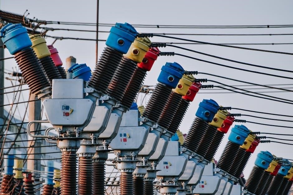
Transformers are essential components in electrical systems, enabling voltage conversion through electromagnetic induction. They play a crucial role in modern electronics and power distribution, ensuring efficient energy transfer. Understanding transformer wiring is vital for safe and reliable operation, as improper connections can lead to system failures or safety hazards.
1.1 What is a Transformer?
A transformer is an electrical device that transfers energy between circuits through electromagnetic induction. It consists of two or more insulated wire windings, known as the primary and secondary coils, wound around a common magnetic core. The primary winding is connected to an alternating current (AC) power source, while the secondary winding delivers the transformed voltage to a load. Transformers are designed to increase or decrease voltage levels, making them indispensable in power distribution, electronic devices, and industrial systems. They operate on the principle of mutual induction, where the magnetic field generated by the primary coil induces voltage in the secondary coil. This fundamental concept enables efficient voltage transformation, ensuring compatibility between power sources and electrical loads.
1.2 Importance of Transformer Wiring
Proper transformer wiring is critical for ensuring safe, efficient, and reliable operation of electrical systems. Incorrect wiring can lead to short circuits, overheating, or even complete system failure, posing significant safety risks. Accurate connections guarantee that the transformer operates within its rated voltage and current specifications, maintaining efficiency and preventing damage. Additionally, correct wiring ensures minimal energy losses, reducing operational costs and enhancing overall system performance. Properly wired transformers also comply with safety standards, protecting both equipment and personnel from potential hazards. Therefore, understanding and implementing correct wiring practices is essential for maximizing the longevity and functionality of transformers in any application.
Transformer Wiring Basics
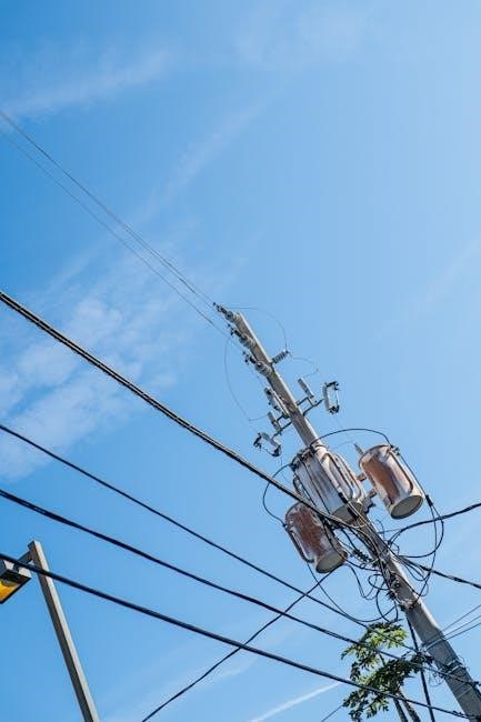
Transformer wiring involves connecting primary and secondary windings to achieve desired voltage and current levels. Proper connections ensure safe and efficient energy transfer, avoiding hazards and maintaining system integrity.
2.1 Understanding Primary and Secondary Windings
The primary and secondary windings are the core components of a transformer, responsible for electromagnetic induction. The primary winding is connected to the input power source, converting electrical energy into a magnetic field. The secondary winding captures this magnetic field and induces an electromotive force, producing the desired output voltage. The number of turns in each winding determines the voltage transformation ratio. Proper identification and connection of these windings are critical to ensure the transformer functions as intended, delivering the correct voltage and current to the load. Understanding their roles and relationships is fundamental for safe and effective transformer wiring.
2.2 Voltage and Current Considerations
Voltage and current considerations are critical in transformer wiring to ensure safe and efficient operation. The primary winding is connected to the input voltage, while the secondary winding provides the output voltage, determined by the turns ratio. Proper voltage matching is essential to avoid damage or inefficiency. Current ratings must also be respected to prevent overheating and ensure reliable performance. Understanding the relationship between voltage and current helps in selecting appropriate wire sizes and protecting the circuit with fuses or circuit breakers. Always refer to the transformer’s specifications to maintain safe operating conditions and prevent overloading, which can lead to system failure or safety hazards.

Transformer Wiring Diagrams
Transformer wiring diagrams are essential for understanding connections. They illustrate primary and secondary winding links, using standard symbols for clarity. These diagrams guide safe and accurate wiring.
3.1 How to Read a Transformer Wiring Diagram
Reading a transformer wiring diagram requires understanding its symbols and structure. Start by identifying the primary and secondary terminals, usually marked as “H1, H2” for primary and “X1, X2” for secondary. Look for input and output sections, with input connected to the power source and output to the load. Colors often code live, neutral, and ground wires. Check for tap settings, which adjust voltage levels. Grounding symbols indicate safety connections. Cross-reference the diagram with the transformer’s nameplate for specifications. Follow the flow of current through the windings, ensuring connections match the diagram. Always consult the user manual for specific instructions, as diagrams may vary by transformer type and application. Proper interpretation ensures safe and correct wiring.
3.2 Common Symbols and Components
Transformer wiring diagrams use standardized symbols to represent components. A circle with two parallel lines inside denotes the transformer itself, while lines connecting to it represent the primary and secondary windings. Terminals are often marked with letters, such as “H1, H2” for primary and “X1, X2” for secondary. Fuses or circuit breakers are shown as small rectangles with lines inside, indicating protection. Grounding symbols, like a triangle or inverted “T,” mark safety connections. Tap changers are represented by multiple lines branching from the windings, allowing voltage adjustments. Colors may differentiate live, neutral, and ground wires. Understanding these symbols is crucial for interpreting the diagram accurately. Always refer to the legend or manual for specific meanings, as variations exist across manufacturers and applications.
Step-by-Step Transformer Wiring Guide
Follow a systematic approach to ensure safe and effective transformer wiring. Start by gathering tools, understanding the wiring diagram, and connecting terminals correctly. Proceed with testing and validation to confirm proper operation and safety.
4.1 Gathering Necessary Tools and Equipment

Gathering the right tools and equipment is the first step in transformer wiring. Essential items include insulated wire cutters, screwdrivers, multimeters, and voltage testers. Ensure all tools are in good condition to prevent accidents. Insulated wires are crucial for safety, while terminal connectors and tape are needed for secure connections. A wiring diagram specific to your transformer model is also necessary for guidance. Proper personal protective equipment, such as gloves and safety glasses, should always be worn. Having all materials ready ensures efficiency and reduces the risk of errors during the wiring process. Proper preparation is key to a successful installation.
4.2 Connecting Primary Terminals
Connecting the primary terminals is a critical step in transformer wiring. Always refer to the wiring diagram to identify the correct primary terminals for your transformer. Ensure the input voltage matches the transformer’s primary winding rating. Use insulated wires to connect the primary terminals to the power source. Before making connections, verify that the circuit is de-energized to avoid electrical shock. Strip the wire ends and securely attach them to the terminals using screws or connectors. Double-check the polarity and wiring configuration to prevent phase mismatches. Properly tightened connections are essential to avoid overheating or arcing. If unsure, consult the manufacturer’s manual for specific guidance on primary terminal connections.
4.3 Connecting Secondary Terminals
Connecting the secondary terminals ensures the transformer delivers the correct output voltage to the load. Begin by identifying the secondary terminals using the wiring diagram. Match the load’s voltage requirements to the secondary winding’s rating to avoid damage or inefficiency. Use insulated wires for connections and ensure the transformer is de-energized before proceeding. Strip the wire ends and securely attach them to the terminals, verifying polarity if necessary. Tighten all connections firmly to prevent loose wires, which can cause arcing or overheating. If the transformer has multiple secondary windings, connect them in series or parallel as specified by the diagram. Always consult the manufacturer’s manual for specific guidance on secondary terminal configurations and load compatibility.
4.4 Testing the Transformer
Testing the transformer ensures proper functionality and safety. Begin by verifying the primary and secondary voltages using a multimeter. Measure the input voltage at the primary terminals and compare it to the rated value. Next, check the output voltage at the secondary terminals to ensure it matches the expected level. Test for continuity between the primary and secondary windings to confirm they are not shorted or open. Inspect all connections for tightness and proper insulation. Use a megohmmeter to check insulation resistance if necessary. Finally, ensure the transformer is grounded correctly to prevent electrical hazards. Always de-energize the transformer before performing tests and follow safety guidelines to avoid injury or damage.

Types of Transformers and Their Wiring
Transformers come in various types, each suited for specific applications. Single-phase, three-phase, step-up, step-down, and high-frequency transformers each have unique wiring requirements based on their intended use and system configuration.
5.1 Single-Phase Transformer Wiring
Single-phase transformers are widely used in residential and light commercial applications, providing a straightforward wiring process. They consist of primary and secondary windings, with the primary connected to the AC power source and the secondary supplying the load. Proper wiring involves identifying the terminals, ensuring insulated wires are securely connected, and following the transformer’s wiring diagram. The primary side is typically connected to the mains supply, while the secondary side is connected to the desired load. It’s crucial to match the voltage ratings and ensure proper grounding for safety. Regular maintenance and adherence to safety protocols are essential to prevent overheating or electrical hazards. Always refer to the manufacturer’s guidelines for specific wiring instructions.
5.2 Three-Phase Transformer Wiring
Three-phase transformers are commonly used in industrial and high-power applications, requiring precise wiring to ensure efficient operation. The wiring involves understanding Delta (Δ) and Wye (Y) configurations, which determine how the primary and secondary windings are connected. Proper connections are critical to avoid issues like voltage imbalance or overheating. Always refer to the transformer’s wiring diagram and manufacturer guidelines for specific instructions. Grounding is essential for safety, and all connections must be secure to prevent electrical hazards. Three-phase wiring is more complex than single-phase, so adhering to best practices and safety protocols is vital. Regular maintenance and inspection are recommended to ensure optimal performance and longevity of the transformer.
5.3 Step-Up and Step-Down Transformers
Step-up and step-down transformers are designed to increase or decrease voltage levels in electrical circuits. A step-up transformer boosts voltage, while a step-down transformer reduces it. Both are crucial for matching voltage requirements in power distribution systems. The primary and secondary windings determine the transformation ratio, with more turns on the secondary for step-up and fewer for step-down. Proper wiring is essential to ensure safe and efficient operation, especially at high voltages. These transformers are widely used in power transmission, industrial machinery, and electronic devices. Always follow safety protocols and manufacturer guidelines to avoid electrical hazards. Efficient design and regular maintenance are key to minimizing energy losses and ensuring optimal performance.
5.4 High-Frequency Transformer Wiring
High-frequency transformer wiring is specialized for applications requiring efficient energy transfer at elevated switching frequencies. These transformers are commonly used in switch-mode power supplies, RF circuits, and resonant converters. Proper wiring ensures minimal signal loss and prevents electromagnetic interference (EMI). High-frequency transformers often utilize specific materials and designs to minimize parasitic inductance and capacitance. Insulation and wire routing are critical to maintain high efficiency and prevent voltage spikes. Grounding and shielding are essential to suppress noise and ensure stable operation. Regular maintenance, such as inspecting connections and replacing worn insulation, is vital for longevity. Always follow manufacturer guidelines for wiring high-frequency transformers to optimize performance and safety in demanding applications.
Transformer Grounding and Safety
Proper grounding ensures safety by preventing voltage spikes and electrical shocks. Follow grounding steps carefully and adhere to safety guidelines to avoid hazards during transformer operation.
6.1 Importance of Proper Grounding
Proper grounding is critical for ensuring the safety and reliability of transformer operations. It protects against voltage spikes, electrical shocks, and equipment damage by providing a safe path for fault currents to earth. Grounding also helps maintain stable voltage levels and prevents overvoltage conditions, which can damage insulation and lead to system failures. Additionally, proper grounding enhances personnel safety by reducing the risk of electric shock during maintenance or operation. It also ensures compliance with electrical safety standards and codes. Without adequate grounding, transformers and connected equipment can be exposed to hazardous conditions, leading to potential malfunctions or fires. Thus, grounding is a non-negotiable aspect of transformer wiring to ensure safe, efficient, and reliable operation.
6.2 Safety Tips for Transformer Wiring
When working with transformer wiring, safety is paramount to prevent accidents and ensure reliable operation. Always disconnect the power supply before starting work, and verify that the transformer is de-energized using appropriate test equipment. Use insulated tools and wear protective gear, including gloves and safety glasses, to minimize the risk of electric shock. Ensure all connections are secure and follow the wiring diagram to avoid short circuits. Never overload the transformer beyond its rated capacity, as this can lead to overheating and failure. Keep the work area well-ventilated and away from flammable materials. Regularly inspect wires and terminals for damage or wear, and replace them if necessary. Adhering to these safety practices helps protect both personnel and equipment, ensuring a safe and efficient transformer wiring process.
Troubleshooting Common Issues
Identifying and resolving transformer wiring issues requires attention to detail. Common problems include short circuits, open circuits, and overheating. Use multimeters to test voltage and resistance, and thermal imaging to detect hotspots. Always refer to the wiring diagram to trace connections and ensure proper installation. Addressing faults early prevents further damage and ensures reliable operation.
7.1 Identifying Common Wiring Issues
Common transformer wiring issues include short circuits, open circuits, and overheating. These problems often stem from improper connections, loose terminals, or damaged insulation. To identify issues, inspect the wiring for signs of wear or damage. Use a multimeter to test for continuity and resistance, ensuring alignment with the wiring diagram. Overheating can be detected using thermal imaging or by checking for unusual warmth during operation. Additionally, verify that the transformer is correctly rated for the applied voltage and current. Faulty connections or mismatched loads can lead to inefficiency or failure. Always follow proper testing procedures to pinpoint the root cause before attempting repairs.
7.2 Tools for Diagnosing Transformer Problems
Diagnosing transformer issues requires specialized tools to ensure accuracy and safety. A digital multimeter is essential for measuring voltage, current, and resistance, helping to identify shorts or open circuits. Thermal imaging cameras detect overheating, a common sign of internal faults. Insulation testers verify the integrity of the transformer’s insulation, preventing leaks or arcing. Oscilloscopes analyze waveforms to detect distortions or noise in the output. Additionally, transformer test kits and winding resistance meters provide detailed insights into the coil conditions. Always use these tools in conjunction with the transformer’s wiring diagram to pinpoint issues efficiently. Proper tool usage ensures reliable diagnostics, preventing further damage and ensuring safe, effective repairs.

Advanced Transformer Wiring Topics
Advanced transformer wiring involves high-frequency applications, series/parallel connections, and specialized configurations for industries like telecommunications. These topics require in-depth knowledge for optimal performance and customization in complex systems.
8.1 Series and Parallel Connections
Series and parallel connections in transformer wiring allow for customized voltage and current configurations. In series connections, transformers are linked to increase total voltage, while parallel connections share current loads, enhancing power capacity. Proper matching of transformer specifications is crucial to avoid overload or imbalance. For series connections, ensure transformers have identical voltage ratings, and for parallel, they must have the same voltage and phase shift. This configuration is ideal for high-power applications or systems requiring flexibility. Always calculate combined voltage or current ratings and verify compatibility before implementation. These techniques are widely used in industrial and high-frequency applications for efficient power distribution and system optimization. Refer to detailed wiring diagrams for safe and accurate connections.
8.2 Transformer Wiring in Specific Applications
Transformer wiring varies significantly across different applications, requiring tailored approaches for optimal performance. In high-frequency applications, such as switch-mode power supplies, transformers are designed with materials like ferrite cores to minimize losses and handle harmonic currents, often necessitating specialized winding techniques. Industrial power distribution frequently employs Delta or Wye configurations, each with distinct wiring requirements to meet load demands and voltage regulation needs. Audio equipment may utilize transformers to isolate circuits and reduce electromagnetic interference, while medical devices require high-isolation transformers to ensure patient safety. In renewable energy systems, transformers must adapt to variable input voltages, ensuring efficient energy transfer. Always consult application-specific wiring diagrams and adhere to safety standards to ensure proper installation and operation, preventing potential hazards and ensuring reliability.
Maintenance and Best Practices
Regular inspection of transformer wiring ensures longevity and safety. Check for wear, damage, or overheating. Proper grounding and insulation are critical for preventing failures and hazards.
9.1 Regular Maintenance Tips
Regular maintenance is crucial for ensuring transformer longevity and reliability. Start by visually inspecting the wiring and connections for signs of wear or damage. Check for loose terminals, frayed wires, or corrosion, as these can lead to electrical issues. Ensure all connections are secure and properly tightened. Next, verify that the transformer is adequately grounded to prevent shocks or short circuits. Insulate wires to avoid heat buildup and potential fires. Schedule periodic professional inspections, especially for high-voltage transformers. Keep the transformer clean and free from dust, which can cause overheating. Replace any damaged components promptly to maintain efficiency and safety. Regular maintenance not only extends the lifespan of the transformer but also ensures optimal performance and prevents unexpected failures.
9;2 Best Practices for Longevity
To ensure transformer longevity, adhere to best practices in installation and operation. Always follow the manufacturer’s guidelines for wiring and connections. Use appropriate materials and tools to prevent damage during installation. Avoid overloading the transformer, as this can lead to overheating and premature wear. Monitor operating temperatures and ensure adequate cooling systems are in place. Protect the transformer from environmental hazards such as moisture and humidity, which can degrade insulation and cause faults. Implement surge protection devices to safeguard against voltage spikes. Regularly review and update wiring configurations to meet changing electrical demands. By following these practices, you can maximize the transformer’s lifespan, minimize downtime, and ensure reliable performance over time;
